Before proceeding please check which Module-X model is being connected.
This chapter is about Module-X5 [GK_MX5]
Module-X5 with pigtail:
The Module-X5 comes with a pigtail existing of:
1.I/O cable
Version: v5- AV0017-04 -TRVVSP *7P+F+AL +B OD:8. 7±0.2mm
2.Ethernet cable
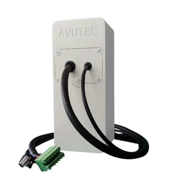
Module-X4 with dual pigtail
Wiring diagram of the Module-X - I/O cable
P1 |
Color |
Description |
|
|---|---|---|---|
1 |
orange |
RS485- (B) |
|
2 |
white/red |
Wiegand D0 |
|
3 |
black |
Relay_B COM |
|
4 |
white/black |
Relay_A NO |
|
5 |
red |
Wiegand D1 |
|
6 |
black/orange |
RS485+ (A) |
|
7 |
brown |
GND - NOT USED |
|
8 |
black/brown |
Relay_B NO |
|
9 |
blue |
Relay_A COM |
|
10 |
black/blue |
CTL IN1 |
>2.2=high |
11 |
green |
EXT power in GND |
|
12 |
black/green |
Wiegand / OSDP GND in |
|
13 |
yellow |
EXT power in |
24VDC~48VDC |
14 |
black/yellow |
Wiegand / OSDP +12V in |
Wiegand - Connecting with the Atrium A22K controller
Module-X4 - I/O cable |
A22K |
|---|---|
Wiegand D0 (white/red) |
D0 |
Wiegand D1 (red) |
D1 |
Wiegand GND in (black/green) |
GND |
Wiegand +12V in (black/yellow) |
12V |